Top Causes of High-Voltage Contactor Failure and Preventive Maintenance
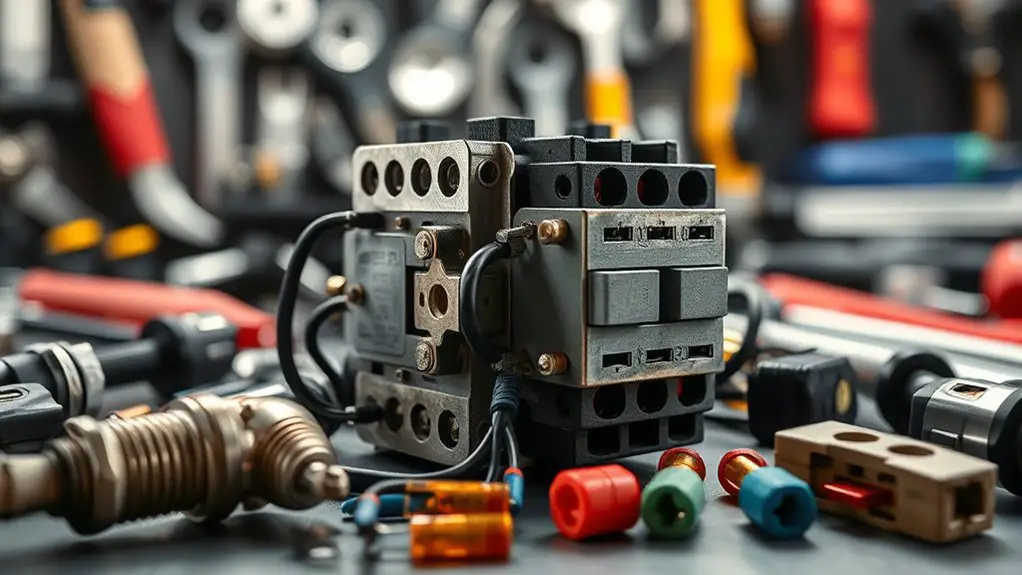
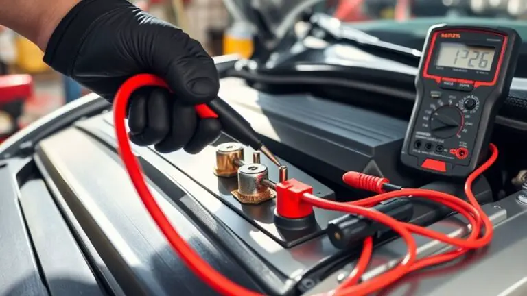
Top causes of high-voltage contactor failure include arc wear, coil overheating, improper sizing, and aging contacts. Contamination and environmental factors rise contact resistance, while mechanical wear and linkage fatigue undermine operation. Inadequate sealing, breather issues, and insulation degradation compound risk. For preventive maintenance, you’ll monitor arc rate, track coil temperatures, verify inrush handling, and clean surfaces per guidance. Establish routine inspections, lubrication, and thermal margins, with traceable corrective actions. Stay vigilant—the next steps reveal actionable, step-by-step safeguards.
Common Arc-Rate and Contact Wear Causes

Common arc-rate and contact wear arise from electrical and mechanical stress that progressively degrade a high-voltage contactor. You assess initiation and progression factors by measuring arc intensity and monitoring contact material condition. When switching, transient currents create localized heating, erosion, and oxide formation on contact material, increasing resistance and wear rate. Track contact separation speed, bounce, and dwell time to determine exposure duration and stress cycles. Use systematic inspections to identify pitting, glazing, and material transfer between contacts and electrodes. Employ preventative strategies: select material with appropriate hardness and conductivity for your duty, apply protective coatings if compatible, and guarantee clean mating surfaces to minimize arcing seeds. Implement controlled operating routines, including gradual load ramping and proper circuit interruption sequencing. Document all fault events, quantify wear progression, and schedule timely retirements before contact performance degrades. Your goal is a predictable wear curve, stable arc behavior, and reliable interruption performance through disciplined maintenance.
Coil Overheating and Thermal Stress
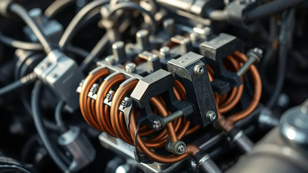
Coil overheating and thermal stress become a natural continuation after addressing arc-rate and wear, because repeated switching and sustained currents spark temperature builds in the coil windings and insulation. You monitor coil temperature rise during duty cycles, noting how insulation degrades when exposed to excess heat. Implement robust thermal management by deploying adequate cooling paths, verifying coolant flow, and ensuring heat sinks are free of obstructions. Track winding resistance changes, which signal thermal aging, and use thermography to spot hotspots before insulation damage occurs. Maintain consistent coil insulation clearances, and replace aging varnish or epoxy that loses dielectric strength under heat. Establish conservative temperature targets tied to insulation class, and enforce derating for high-load periods. Preventive checks include verifying ambient limits, ventilation effectiveness, and enclosure ventilation when switching frequencies increase. By integrating disciplined monitoring, you reduce failure risk and extend contactor life without compromising performance or operator freedom.
Improper Sizing and Inrush Handling
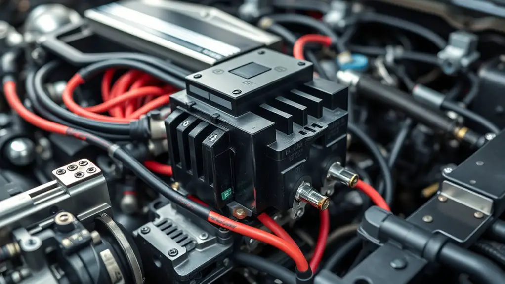
Inrush current behavior sets the baseline for sizing and protection strategies, so you’ll examine Inrush Current Basics to predict transient demand. You’ll use Sizing for Transients to guarantee contactor ratings align with anticipated surge and duty cycle, preventing nuisance trips and contact wear. This discussion also links to Coil and Contact Wear, highlighting how improper sizing accelerates erosion and reduces life under repeated transients.
Inrush Current Basics
Inrush current, the surge that occurs when a high-voltage contactor first energizes, is highly sensitive to sizing and how the surge is managed. You assess the electrical characteristics to predict peak levels and duration, then plan a controlled energizing sequence. Know that a rapid impulse can exceed contacts’ ratings, accelerate wear, and reduce lifespan if not tamed. Use soft-start strategies or pre-charge paths where appropriate, and guarantee timing aligns with network impedance and supply stability. Document allowable inrush margins and verify by test data from similar installations. Maintain clear maintenance procedures that track observed deviations, component aging, and protective device coordination. By focusing on measurement, repeatability, and disciplined practice, you reduce nuisance tripping, thermal stress, and unexpected outages while preserving system reliability and freedom to operate.
Sizing for Transients
When sizing for transients, you must anticipate improper sizing and its impact on inrush handling by defining clear margins between actual surge needs and component ratings. You’ll perform a disciplined transient analysis that maps peak currents to least-favorable loading events, ensuring margins accommodate aging and tolerance. Assess load characteristics—motor starts, transformer energizations, and short-cycle operations—to quantify peak demand as a design envelope, not a single value. Choose contactor ratings with headroom for both steady-state and transient peaks, and specify protective delays or soft-start strategies to absorb surges without nuisance trips. Document assumptions, test plans, and acceptance criteria so future maintenance can verify adherence. Maintain a conservative bias toward reliability, recording deviations and updating the model with field feedback to sustain safe, continuous operation.
Coil and Contact Wear
Coil and contact wear is directly impacted by improper sizing and insufficient inrush handling, so you’ll want to link sizing outcomes to wear patterns. In this section, you’ll align coil resistance and contact alignment with operating stresses, documenting how under- or over-sizing exaggerates arc energy and mechanical fatigue. Methodical checks guarantee the coil experiences stable current, reducing thermal cycling and wear progression. You’ll implement preventive steps: verify coil resistance against nominal data, confirm contact alignment remains within tolerance, and incorporate staged inrush limits to flatten transients. The table below visualizes relationships between sizing decisions and wear indicators.
| Sizing Factor | Wear Outcome |
|---|---|
| Inrush handling | Arc energy, contact pitting |
Aging Contacts and Material Degradation
Aging contacts and material degradation directly impact contact reliability and interrupt the safe operation of high-voltage contactors. You’ll examine how aging alters contact surfaces, coatings, and base metals, reducing current carrying capacity and increasing erosion. Focus on predictable degradation modes: oxidation, micro-cracking, creep under load, and metal transfer during switching. Implement a maintenance mindset that tracks changing contact resistance, contact bounce, and arc stability over time. Prioritize preventive actions: establish baseline contact life and schedule timely inspections before performance slips, and use data-driven thresholds to trigger replacements. Emphasize materials selection early in the lifecycle; choose alloys and coatings that balance hardness, conductivity, and wear resistance for your duty cycle. Document operating conditions, including duty cycles and environmental stresses, so you can forecast remaining life. Regularly verify proper seating, alignment, and torque, and ascertain spare parts are available to maintain consistent contact lifespan across the fleet.
Contamination and Environmental Effects
Contamination and environmental effects directly influence contact performance by introducing foreign materials and conditions that alter surface interactions and heat dissipation. You assess how airborne particles and moisture interact with contact surfaces, changing contact resistance and arc behavior. In practice, environmental exposure dictates contamination pathways; you map entry points, seal integrity, and enclosure cleanliness to prevent degradation. You identify dust accumulation as a primary factor in junctions, ferrules, and terminal interfaces, where insulating layers or conductive bridges can form, affecting current sharing and hotspot formation. You implement targeted inspections to verify gaskets, breathers, and venting are intact, and you schedule cleaning routines that minimize risk of surface damage. You document environmental trends, correlate exposure events with maintenance logs, and adjust filtration or enclosure upgrades accordingly. Your preventive measures emphasize controlled environments, timely decontamination, and robust sealing to maintain predictable dielectric performance and safe operating temperatures.
Mechanical Wear and Linkage Fatigue
Mechanical wear and linkage fatigue directly impact contact actuation accuracy and trip reliability. You’ll inspect moving parts for looseness, wear patterns, and stuck safeties, then quantify tolerance deviations against the manufacturer’s specifications. Inspect springs, pins, and pivots for progressive elongation or galling, and verify that each linkage path remains free of binding across full travel. Document excursion errors, misalignment, and any uneven opening or closing force, as these indicate evolving mechanical fatigue. Implement a preventive routine that emphasizes consistent lubrication, clean contact surfaces, and scheduled retightening of fasteners to avoid micro-slips that degrade performance. Achieve reliable actuation by performing regular linkage adjustment per procedure, ensuring proper preload and alignment with the actuator and switch points. Record maintenance outcomes, cytoplasm-free measurements, and corrective actions to support trend analysis. Remember, early detection of wear prevents unplanned trips and extends service life while preserving system freedom to operate within defined safety margins.
Electrical Noise, Surges, and Insulation Breakdown
Electrical noise, surges, and insulation breakdown can compromise a contactor’s reliability by introducing erratic switching, premature insulation aging, and potential internal shorting. You’ll recognize that transient spikes and EMI can push contacts into arcing, accelerating wear. Maintain a disciplined approach: identify sources, isolate control circuits, and implement robust noise filtering to preserve clean gate drive and coil energization. Grounding practices matter; ascertain proper electrical grounding to prevent floating potentials that invite unwanted currents. Use shielded cables where practical and route sensitive leads away from high-current troughs. Verify that surge suppression devices are sized for your load profile and that they’re positioned to clamp transients before they reach the coil. Regular insulation resistance checks help detect aging before failure. Design your preventive routine to document surge events, perform insulation tests, and replace aging components proactively. When in doubt, consult manufacturer guidelines to align grounding, filtering, and maintenance with your system’s freedom to operate reliably.
Inadequate Sealing and Breather Issues
Inadequate sealing and breather issues can allow moisture, dust, and corrosive vapors to infiltrate the housing, accelerating corrosion and energizing contamination paths that undermine contactor reliability. You must assess how sealing materials perform under thermal cycling, chemical exposure, and vibration, because degraded seals are a primary risk to arc-quenching surfaces and dielectric barriers. Inspect seals for compression set, cracking, and wear, and verify that gasket profiles match joint geometries to prevent bypass paths. Breather design matters: a properly sized breather with an appropriate desiccant and one-way vent reduces internal humidity without permitting ingress during pressure changes. Choose materials rated for electrical equipment, temperature range, and contamination exposure, and guarantee installation torque maintains sealing integrity without deforming interfaces. Implement routine checks for seal discoloration, moisture buildup, and desiccant saturation. Track replacement cycles, correlating with operating hours and ambient conditions to sustain long-term reliability and predictable performance.
Maintenance Practices and Schedules for Longevity
Establish a routine inspection cadence to monitor key wear points, contact surfaces, and enclosure seals, documenting findings and scheduling corrective actions. Implement periodic contact arc lubrication per manufacturer’s guidance to reduce wear, arcing duration, and reliability risk, while avoiding over-application that can attract dust. Integrate thermal monitoring practices to detect rising temperatures early, triggering maintenance events before performance degrades.
Routine Inspection Cadence
Routine inspection cadence should be defined by equipment criticality, operating environment, and manufacturer guidance, then implemented with regular, documented checks. You’ll establish a schedule aligned to risk, logging each actuation, contact cleanliness, and terminal integrity to prove compliance and extend life. Routine inspection benefits include early fault detection, reduced downtime, and informed maintenance planning, while inspection frequency guidelines guarantee coverage without overtesting. Follow a reproducible template: date, supervisor, findings, action. Maintain traceability and corrective actions tied to mean time between failures. Table below highlights cadence drivers, tasks, and documentation.
| Cadence Driver | Core Task | Documentation |
|---|---|---|
| Criticality | Visual/functional check | Sign-off and timestamp |
| Environment | Contact resistance measurement | Maintenance record |
Contact Arc Lubrication
A structured approach to contact arc lubrication follows from the inspection cadence by focusing on maintaining clean, low-resistance interfaces where arcing occurs. You facilitate reliability by selecting appropriate lubricants and applying them with disciplined control. Assess contact surfaces for wear, contamination, and moisture before lubrication, then document findings to adjust maintenance frequency. Use contact lubrication techniques that minimize residue, avoid carbonizing lubricants, and prevent insulation compromise. Apply lubrication only to specified interfaces, avoiding over-application that traps contaminants or skews resistance readings. Schedule maintenance frequency based on duty cycle, switching frequency, and environmental exposure; increase cadence after events such as overloads or abnormal arcing. Maintain rigorous records, verify arc behavior post-service, and ascertain lubrication aligns with OEM guidelines and safety standards.
Thermal Monitoring Practices
Thermal monitoring should be integrated into the maintenance plan as a continuous, data-driven practice that flags overheating before it affects longevity or safety. You implement a schedule that combines thermal imaging scans with periodic readings from temperature sensors attached at critical contactor points. Establish baseline temperatures under normal load, then track deviations with thresholds tied to apparatus ratings. When anomalies appear, trigger root-cause analysis and targeted interventions—tightening, cleaning, or component replacement as needed. Document trends, not just snapshots, to distinguish transient spikes from progressive wear. Align monitoring frequency with duty cycles and environmental conditions, ensuring alarms are actionable and time-stamped. Regular reviews of sensor placement and calibration keep data accurate, empowering proactive decisions and safer, longer-lasting high-voltage systems.
Frequently Asked Questions
How Do You Predict Contact Wear Rates Under Varying Load Profiles?
You can predict contact wear rates by performing a structured load analysis and applying a wear model to contact life, then validating with measured fault events. Don’t fear variability—normalize current and arcing duty, then fit a regression to wear proxies. You’ll estimate remaining life under each profile, update with real-time data, and implement preventive adjustments. This methodical approach gives you actionable insight while preserving your freedom to optimize operation and maintenance schedules.
What Are the Best Indicators of Impending Coil Insulation Failure?
Coil temperature trends and insulation resistance are your best indicators of impending coil insulation failure. You’ll monitor gradual rises in coil temperature under steady load and compare insulation resistance against baseline values; a persistent decline signals degradation. Regular thermal profiling and DC resistance checks help trend aging. Implement alarm thresholds, document excursions, and correlate with environmental factors. You’ll prioritize proactive maintenance by tagging abnormal readings and scheduling timely coil refurbishment before outright failure.
How to Verify Correct Contact Gap After Installation?
“A stitch in time saves nine,” so here’s the method. You verify contact gap after installation by precisely measuring with a feeler gauge or calibrated gap tool, then perform a dry-run test to observe make/break timing. Record healthy arc-to-arc clearance, adjust as needed via established setpoints. Document installation verification results, recheck after mechanical tightening, and confirm consistent contact alignment. Maintain safe, preventive practice for reliable operation with proper contact adjustment.
Which Diagnostics Detect Partial Discharge in High-Voltage Coils?
Partial discharge is detected by several diagnostic methods: electrical partial discharge (PD) measurement with high-frequency current transformers, ultrasonic PD detection, and transient earth voltage (TEV) sensing. You should implement these detection methods in scheduled tests, correlate PD activity with phase-resolved patterns, and trend PD magnitude over time. Use PD mapping to pinpoint insulation weaknesses, and enforce corrective actions promptly to prevent insulation failure and costly downtime. Maintain calibrated sensors, documented procedures, and objective pass/fail criteria for reliability.
How Does Ambient Humidity Influence Breaker Performance?
Like Odysseus steering home, you’ll see ambient humidity directly affects breaker performance. Humidity effects your contact erosion, insulation reliability, and mis-operation risk, while moisture levels influence leakage paths and arcing propensity. You’ll monitor dew point, ambient RH, and enclosure temps, then apply conditioning or sealing strategies to maintain stable dielectric strength. In practice, you’ll document thresholds, perform regular deaeration if needed, and enforce preventive maintenance to sustain reliable, freedom-loving operation.

