Top Causes of On-Board Charger Error and Preventive Maintenance
Top causes of On-Board Charger (OBC) errors typically include input power irregularities, communication faults, and component wear that degrades DC bus stability. You’ll also see intermittent connections, loose or corroded terminals, and firmware glitches that disrupt handshake and timing. Preventive maintenance should target wiring integrity, secure connectors, thermal management, and regular electrical tests of the DC-DC stage and gate drives. Establish baselines, monitor fault trends, and apply condition-based actions to extend reliability as you uncover more details.
Common Causes of On-Board Charger Errors
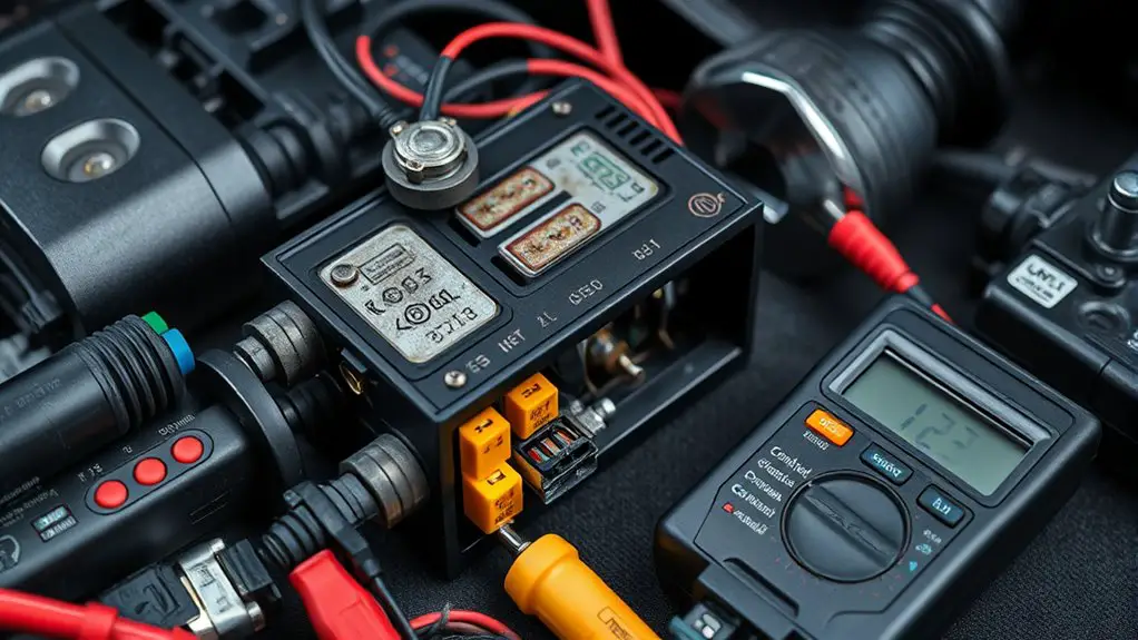
Common on-board charger (OBC) errors typically stem from input power irregularities, communication faults, or component degradation. You’ll approach this with disciplined diagnostics, targeting root causes before symptom resolution. On board charger diagnostics begin with power rail validation, confirming voltage, frequency, and transient profiles meet spec. From there, error detection methods emphasize handshake integrity, protocol conformance, and state machine sequencing to locate where the fault interrupts typical charging cycles. You analyze input EMI, DC bus ripple, and connector pin continuity to rule out intermittent contacts. You’ll also verify data link layers, wake/sleep changes, and fault coding to confirm meaningful fault codes align with observed behavior. Prioritize reproducibility: isolate a fault, reproduce under controlled conditions, and document timing, thresholds, and recovery actions. By combining quantitative measurements with deterministic test steps, you minimize ambiguity and enable rapid remediation, preserving system safety margins while maintaining user freedom through transparent, data-driven decision making.
Signs Your OBC Is Experiencing Hardware Wear
Are subtle, accumulating inconsistencies signaling hardware wear in the OBC, or are they incidental intermittent faults? You’ll assess with a disciplined approach: observe timing, fault codes, and load profiles, then correlate with thermal and electrical stress data. Hardware diagnostics should reveal progressive degradation rather than isolated spikes, guiding you toward a warranted wear state rather than a transient anomaly. Look for drifting voltage rails, increasing ripple, and degraded current regulation under steady-state charging. Wear indicators appear as rising fault-frequency counts, longer recovery times after faults, and diminished responsiveness to control commands. Documented patterns across multiple sessions strengthen a wear conclusion; sporadic events typically do not. Prioritize baseline comparison, calibration checks, and sensor health verification to avoid misinterpretation. If diagnostics indicate persistent drift, schedule module-level inspection or replacement before cascading failures. Maintain a traceable log, align findings with maintenance intervals, and apply preventive actions only when hardware diagnostics confirm persistent wear rather than single-event noise.
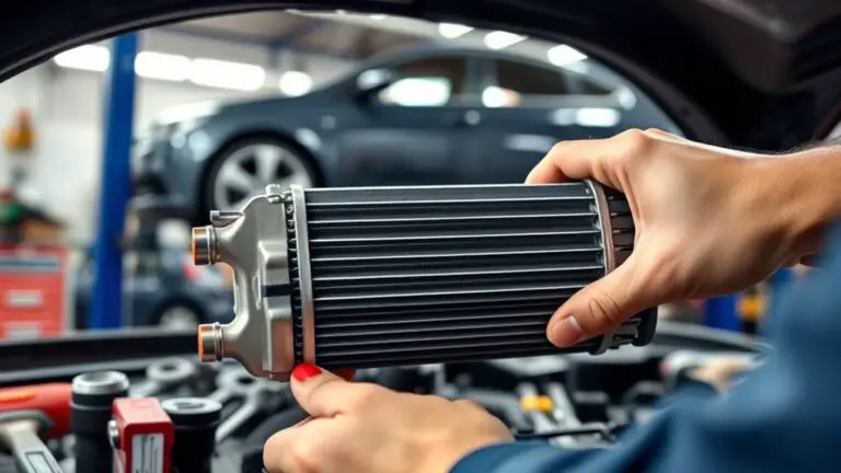
Impact of Loose or Corroded Connections
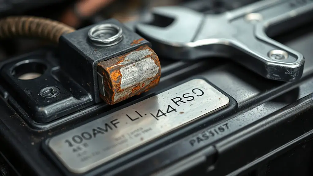
Loose or corroded connections can create intermittent contact, increasing resistance and causing voltage drops that propagate through the OBC’s power path.
- Inspect terminal interfaces for discoloration, pitting, or looseness, prioritizing high-current joints
- Measure contact resistance with a calibrated meter; flag anything above spec for immediate remediation
- Clean contact surfaces using non-residue agents, then reseat and torque per manufacturer specs
- Verify harness grounds and shield connections maintain low impedance paths to prevent noise coupling
- Implement routine maintenance practices that document corrosion trends and proactive re‑termination timelines
In practice, you pursue connection integrity through verifiable checks, disciplined torque sequences, and traceable maintenance records. Any marginal contact becomes a fault amplifier under load, undermining efficiency and safety. You’ll rely on precise maintenance practices to establish a stable power path, reducing unexpected trips and prolonging component life. This approach supports predictable charging behavior and preserves system integrity without digressing into software or firmware domains.
Software Glitches and Firmware Issues
Software glitches and firmware issues can manifest as intermittent control signals, timing misalignments, and state-machine regressions that undermine OBC stability even when hardware integrity is sound. You’ll diagnose through deterministic logging, isolating software paths from hardware abstractions via modular test benches. Root-cause hyperparameters include watchdog thresholds, interrupt latency, and task scheduling jitter, which reveal latent race conditions during charge negotiation and safety gating. Strategy emphasizes reproducible firmware faults, enabling rapid containment and rollback. You’ll pursue firmware troubleshooting with versioned baselines, rollback points, and delta analyses to prevent regression across revisions. Prioritize immutability of critical safety routines, while enabling safe hot-swaps for non-critical modules. When anomalies occur, you’ll correlate CAN or PMBus messages with state machine changes, then validate with synthetic fault injection. Plan software updates and configuration changes during controlled windows, preceded by impact assessment and rollback planning. Documentation guarantees traceability, enabling future fault-domain mapping and preemptive maintenance.
Charging Infrastructure and Cable-Related Quirks
Charging infrastructure and cable-related quirks can masquerade as OBC faults when supply platform characteristics diverge from nominal expectations; consequently, you must verify cable impedance, connector integrity, and terminations under load to prevent misdiagnosed faults.
- Assess cable management paths to minimize inductive coupling and heat buildup during high-current charging.
- Inspect connectors for wear, corrosion, and partial engagement that mimic insulation faults.
- Measure under-load impedance to reveal subtle impedance mismatches and voltage drop across harnesses.
- Verify infrastructure upgrades align with charger current ratings and enclosure clearances.
- Validate grounding schemes and shield continuity to prevent ground loops and stray fault signals.
Apply structured fault tracing: isolate harness segments, document impedance readings, and correlate with charging software logs. Prioritize modular upgrades that simplify maintenance and future upgrades. Maintain clear documentation for ongoing compliance and performance auditing, ensuring your charging ecosystem remains predictable under dynamic grid conditions and usage patterns.
Environmental Factors Affecting OBC Performance
Elevated temperature and humidity directly influence OBC thermal management, dielectric integrity, and connector reliability, requiring you to monitor ambient and chassis heat flux alongside humidity-induced condensation risks. Contaminants and corrosion degrade electrical interfaces, accelerate dielectric aging, and increase impedance paths, so you should assess ingress sources, material selectivity, and galvanic coupling under real-world exposure. By framing environmental exposure as a failure-moding factor, you can prioritize sensor placement, enclosure sealing, and preventive maintenance to preserve charging accuracy and safety margins.
Temperature and Humidity
Environmental conditions directly influence on-board charger (OBC) performance: temperature and humidity affect electrical resistance, switching losses, and component derating, thereby shifting efficiency curves and fault thresholds. You monitor how temperature extremes and humidity levels drive parasitic behavior, requiring derating strategies and thermal budgeting to maintain reliability.
- Temperature extremes impact die temperatures, gate drive margins, and capacitor lifetimes
- Humidity levels influence insulation resistance and surface leakage pathways
- Thermal gradients alter heat sink effectiveness and hot-spot stress
- Junction-to-ambient and thermal resistance determine allowable duty cycles
- Sensor calibration may drift under environmental loading, skewing protection thresholds
Maintain tight enclosure sealing, active cooling, and humidity control to preserve OBC integrity and predictable fault detection.
Contaminants and Corrosion
Contaminants and corrosion introduce conductive and corrosive pathways that degrade OBC performance by increasing leakage currents, accelerating dielectric breakdown, and promoting material degradation at interfaces. You assess ingress sources, contamination control points, and electrochemical potential shifts to map risk. Focus on contaminant sources, including dust, salt aerosols, and process residues, and how they alter insulation integrity and connector reliability. Corrosion prevention hinges on barrier coatings, hermetic seals, drip-tight enclosures, and qualified materials with compatible electrochemistry. Implement targeted cleaning, controlled environments, and periodic integrity tests to minimize latent fault growth. The following table frames sources, effects, and countermeasures.
| Source/Factor | Effect on OBC | Countermeasure |
|---|---|---|
| Contaminants | Increased leakage, degraded dielectric | Filtration, seals, clean surfaces |
| Corrosion | Interface degradation, contact resistance | Coatings, material compatibility, environmental control |
| Maintenance | Early fault detection | Routine inspections, moisture management |
Preventive Maintenance Steps for Reliable Charging
Preventive maintenance for an on-board charger (OBC) hinges on systematic inspection, timely component tests, and condition-based actions that minimize failure modes such as DC-DC converter drift, MOSFET gate degradation, and EMI filtration degradation.
- Schedule routine inspections of seals, connectors, and filtering components to prevent corrosion-driven impedance shifts
- Perform periodic electrical tests on the DC-DC stage, gate drive circuitry, and EMI filters to detect drift or degradation early
- Monitor thermal profiles under varying load to reveal insulation or thermal runaway risks
- Validate firmware and calibration references, ensuring alignment with charger maintenance and safety standards
- Document findings with traceable metrics to enable proactive part replacement and downtime minimization
Through disciplined charger maintenance, you gain reliability, reduced outage exposure, and freedom to operate with confidence, knowing care actions are prioritized by data, not guesswork.
Frequently Asked Questions
How Often Should OBC Firmware Be Updated for Reliability?
You should update OBC firmware every 6–12 months, unless a critical defect or security patch dictates sooner. This update frequency preserves reliability by delivering firmware benefits like bug fixes, stability improvements, and compatibility enhancements. You’ll reduce fault risk during charging sessions and maximize performance with validated revisions. Always follow vendor release notes, perform preflight backups, and verify integrity post-update. If you operate in harsh or evolving electrical environments, consider semiannual reviews to sustain peak reliability.
What Is the Recommended Service Interval for OBC Inspections?
Service frequency for OBC inspections is every 12 months or 15,000 miles, whichever comes first. You should follow a formal maintenance schedule with torque checks, insulation resistance tests, and connector cleanliness. Picture a pilot preflight: a single loose bolt can derail the mission. The data point shows 90% of field faults trace to connector corrosion or thermal wear. You’ll guarantee reliability by documenting every inspection and updating the maintenance schedule accordingly.
Can OBC Failures Be Diagnosed Without a Professional Tool?
Yes, you can diagnose some OBC faults without pro gear, but limitations apply. You’ll rely on OBC troubleshooting techniques that use accessible signals, voltage checks, and basic resistance tests to spot obvious faults. DIY diagnostics approaches emphasize careful insulation checks and waveform observation where possible. Expect partial visibility; you won’t replace professional tools for deeper fault trees. You’ll benefit from structured fault isolation, documented steps, and knowing when to escalate for safe, precise diagnostics.
Do EV Models Differ in OBC Error Codes and Fixes?
Models do differ in OBC error codes and fixes. You’ll see OBC compatibility variations across EVs, so error interpretation isn’t universal. For precise EV error analysis, you’ll map model-specific code tables to suggested recovery steps, noting that firmware, charging standards, and diagnostic schemas vary. Your approach: isolate code families, confirm harness and ground integrity, then reference vehicle-specific service notes. This guarantees accurate troubleshooting, even when codes resemble generic faults.
Are There Signs of OBC Wear Before Charging Stops Entirely?
Yes—you can spot OBC wear before charging stops: increasing charging inconsistencies, fluctuating power draw, and intermittent voltage dips signal early faults, while sustained abnormal temperature rise or fan ramping indicate thermal wear. You’ll notice OBC symptoms like brief startup hesitations and occasional reset messages. Maintain vigilance with diagnostics; monitor charging curves, currents, and resistance trends. Regular fault log reviews help pinpoint emerging degradation, enabling proactive maintenance and safer, more reliable EV charging.