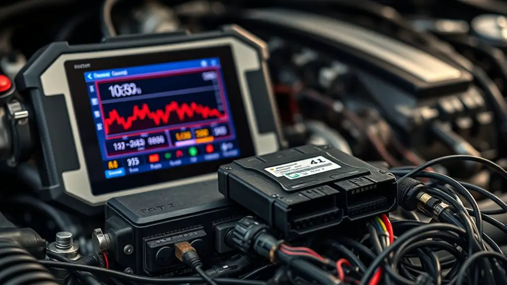
Using Live Data to Pinpoint No Communication With ECU
To pinpoint ECU no communication fast, you start by establishing a live-data baseline so you can spot anomalies in cadence and sensor reports. Next, verify power, grounding, and network integrity to rule out supply drops or high-impedance paths. Check wake-up signals and diagnostic lines to confirm the ECU is entering ready state. Monitor protocol timing and bus activity to catch framing or arbitration issues. If issues persist, follow signals from wiring to firmware status—you’ll uncover where things fail, and you’ll uncover more soon.
Establishing Baseline: What Live Data Should Look Like
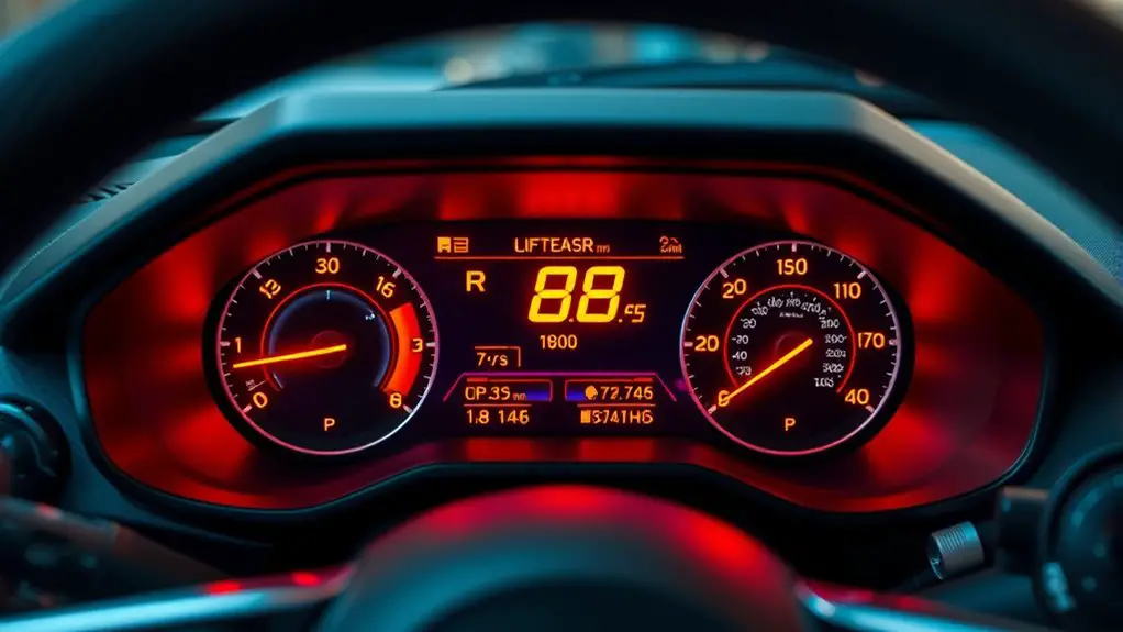
Establishing baseline for live data means defining what normal, healthy ECU communication looks like under typical operating conditions. You’ll identify baseline characteristics that reflect steady-state sensor reports, consistent cadence of messages, and stable bus timing. In this frame, you assess expected parameters such as RPM, injector pulse width, MAP/MAF readings, voltage rails, and sensor diagnostics, noting their usual ranges and response patterns. You’ll map how data should trend during idle, acceleration, and deceleration, recognizing normal jitter versus meaningful shifts. Document the reference dataset you’ll compare against when symptoms arise, and guarantee you account for vehicle variants, firmware revisions, and expected cyclical updates. Your aim is to establish a precise, reproducible profile that distinguishes healthy chatter from anomalies. This baseline serves as a control, not a conclusion, guiding you to detect deviations without overreacting to benign fluctuations. Maintain discipline in recording, labeling, and revisiting baseline characteristics and expected parameters as the system evolves.
Verifying Power, Grounding, and Network Integrity
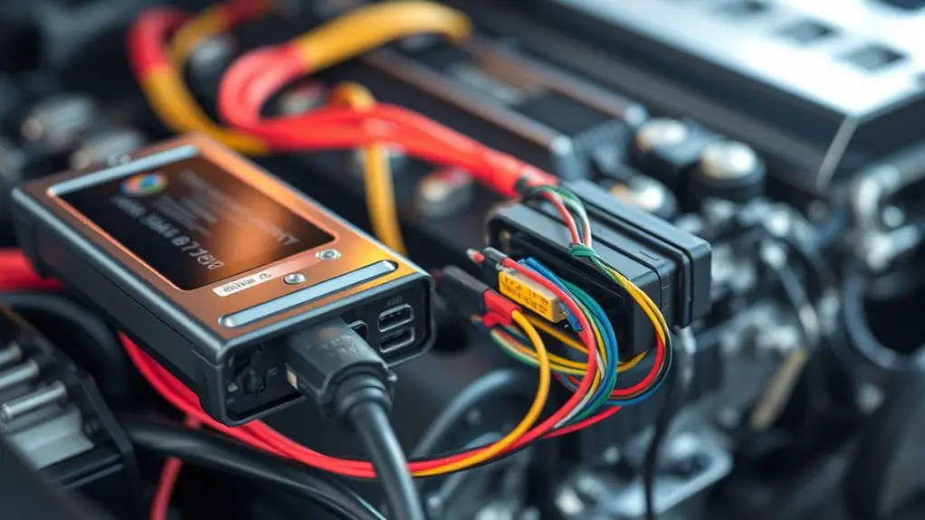
To verify power, grounding, and network integrity, start by confirming that the ECU and associated controllers receive stable supply voltages within spec and that grounds are solid and low-impedance. Then assess the backbone network for proper node addressing, bus termination, and fault isolation to prevent false negatives in live data.
To verify power, grounding, and network integrity: ensure stable ECU supply, solid grounds, proper bus termination, and fault isolation for reliable live data.
- Check power distribution paths for voltage drop under load and verify supply rails meet ECU tolerances
- Validate grounding techniques, ensuring low-impedance return paths and chassis ground continuity
- Inspect network integrity with correct termination, clock alignment, and minimal bus reflections
- Confirm wake/sleep control signals don’t introduce unintended impedance or drift in the system
Maintain rigorous measurement methodology, logging voltages, currents, and resistance with calibrated tools. If anomalies appear, isolate sections, reseat connectors, and recheck grounding. This discipline prevents misinterpretation of data and supports reliable pinpoints in ECU communication, keeping exploration efficient and free from unnecessary detours.
Checking ECU Wake-Up and Diagnostic Line Signals
You’ll now focus on the ECU wake-up and diagnostic line signals, building on the prior checks of power, grounding, and network integrity. You assess wake-up pulses, K-line/L-line states, and diagnostic request/response lines for proper idle, active, and resting conditions. Look for correct voltages, edge shifts, and timing windows that indicate the ECU is awake and listening. Verify that wake-up signals occur within expected intervals and that diagnostic lines respond to requests without excessive latency or jitter. Monitor for contention or pull-up/pull-down conflicts that could distort signal edges, and confirm that impedance matches the expected bus characteristics to preserve signal integrity. Document anomalies such as stuck-at, shorted, or floating lines, and correlate them with ECU diagnostics results. If wake-up signals are absent or unreliable, isolate wiring, connectors, and interface modules. Precise signal verification enables you to distinguish genuine ECU non-communication from transient noise.
Monitoring Communication Protocols and Bus Activity
Monitoring communication protocols and bus activity involves systematic observation of how the ECU participates in the network, including message timing, framing, and error handling. You’ll quantify data packet flow, verify signal integrity, and perform protocol analysis to detect anomalies. Focus on timing jitter, frame structure, and retry patterns to reveal subtle faults that standard checks miss.
Monitoring protocol health through timing, framing, and error handling reveals subtle bus faults and idle patterns.
- data packet timing anomalies and sequencing
- signal integrity under load and cross-talk
- protocol analysis across bus states and error counters
- bus monitoring for idle gaps, arbitration, and bus idle timeout
This approach lets you map the real network behavior, not just the ECU’s nominal status. You’ll differentiate transient glitches from persistent faults, identify failing nodes, and assess whether the protocol constraints are honored end-to-end. Maintain precise logs, correlate timestamps, and annotate any irregular frames. By staying disciplined and concise, you preserve freedom to act quickly when concrete issues emerge.
Isolating Faults: From Wiring to ECU Firmware Status
Isolating faults requires tracing the fault source across the chain—from wiring harnesses and connectors to the ECU’s firmware—and ruling out each layer methodically. You’ll assess fault identification by verifying continuity, resistance, and connector integrity, then move inward to signal integrity at each link. If a harness or pin is suspect, you replace or repair before testing communications again. For the ECU firmware status, you confirm that the microcontroller boot sequence and firmware checksum pass, ensuring no corrupted code blocks the bus. Document findings succinctly to avoid circular reasoning and maintain a clear trail for future diagnostics. The table below highlights where to focus next, depending on observed symptoms.
| Layer | Key check | Expected result |
|---|---|---|
| Wiring/Connectors | Continuity and contact resistance | Within spec, no opens or shorts |
| Signal integrity | Oscilloscope probe results | Clean edges, stable levels |
| ECU firmware | Boot checksum | Valid, non-corrupt |
Frequently Asked Questions
How Do I Confirm Proper CAN Bus Termination at Each End?
Nope, you confirm CAN bus termination by measuring end-to-end resistance and watching for signal reflections. At each end, make certain termination resistors are 120 ohms across CAN_H and CAN_L, with no parallel paths bypassing them. Use a differential scope or CANalyzer to verify stable communication integrity under load; any reflected edge indicates improper termination. If you see reflections, re-check wiring, stubs, and resistor placement until the bus remains clean and stable.
What Is Normal Flash Memory Behavior During ECU Wake-Up?
When the ECU wakes up, flash memory typically remains idle until the microcontroller initiates a read or write sequence, then access latency is static and predictable. During wake, you should see no bursts of random writes unless a firmware integrity check or calibration update starts. You’ll observe sequential access patterns and brief EEPROM/flash controller initialization. If flash memory shows repeated retries or unexpected CRC errors, re-check wake-up timing, power rails, and bootloader configuration for ECU wake up.
Can Intermittent Sensor Faults Mask ECU No-Communication Errors?
Intermittent faults can mask ECU no-communication errors by masking watchdog timers and delaying negotiation, so you see sporadic bus activity rather than a clean fail state. Yes, intermittent faults may suppress clear “no communication” indicators, while sensor diagnostics test for plausibility, not always link integrity. You’ll need correlation of live data with bus timing and error counters, plus cross-checks of sensor outputs, to confirm real ECU comm loss rather than transient faults.
How to Differentiate Between Tool Timeout Vs Actual Bus Collision?
Yes, you can differentiate: tool timeout implies no timely communication, while a bus collision disrupts multiple nodes. You’ll observe tool response timing gaps versus abrupt, simultaneous errors in multiple communication signals. Use bus analysis to compare signal integrity, error detection codes, and retries. If responses consistently miss deadlines without conflicting frames, it’s a timeout; if many nodes show corrupted frames or CRC errors at once, it’s a collision. Maintain rigorous logging of timestamps and error flags.
Do Wake-Up Patterns Vary by Different Vehicle Models?
You’ll notice that wake-up patterns do vary by model differences, so you’ll see distinct timings in ECU communication across vehicles. When you test, treat the vehicle wake up like a gate opening, with diagnostic tools as your key. You’ll map timing, note anomalies, and infer constraints. Your approach remains precise and analytical, maintaining freedom in method while documenting model differences and their impact on ECU communication for reliable diagnostics.

