How to Trace Wiring Problems Using a Wiring Diagrams
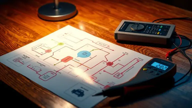
To trace wiring problems with a diagram, start by locating the legend and symbols, then map the circuit from the power source through breakers to the load. Identify hot, neutral, and ground conductors, and verify each junction against the schematic. Use a multimeter to check voltage and continuity, documenting readings precisely. Flag discrepancies with concise notes, then isolate faults by tracing power and signal paths step by step. With careful logging, you’ll uncover corrective actions and gain deeper system insight as you proceed.
Understanding Wiring Diagrams: Symbols and Legend
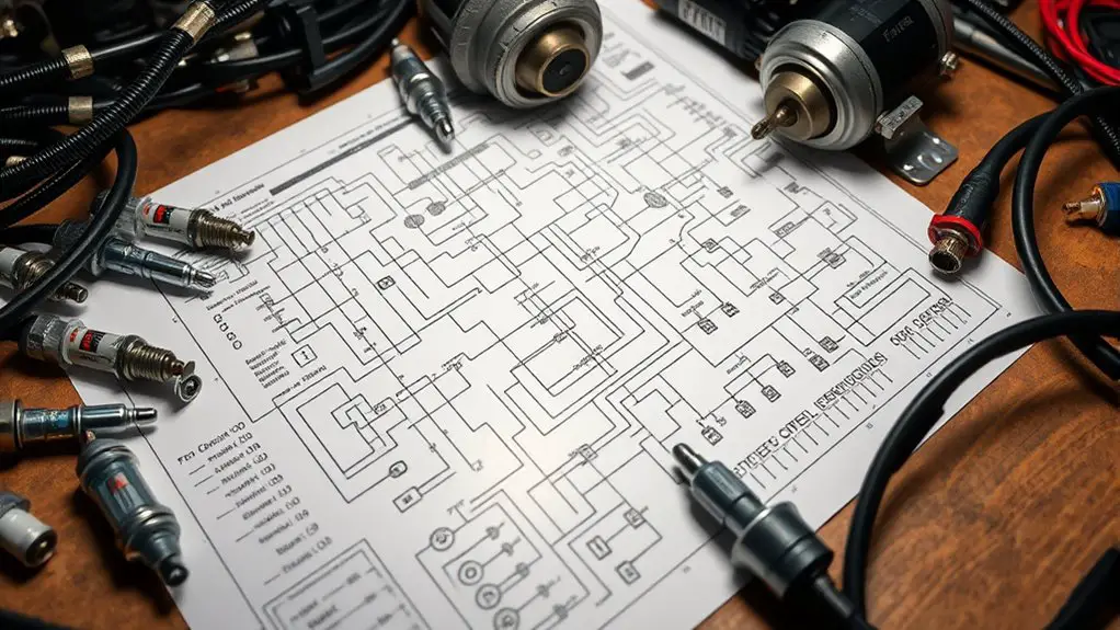
Wiring diagrams use standardized symbols to represent components and connections, with a legend explaining what each symbol means. You’ll approach diagrams as a language, where every mark has intent and traceable meaning. In this section, you focus on understanding symbols interpretation and how the legend makes sense of the drawing. You’ll identify switches, fuses, relays, and conductors by their shape, line type, and placement, then cross-check with the legend to confirm function and path. Keep the legend close at hand and reference it before testing any circuit, so misinterpretations don’t lead you astray. Symbols interpretation hinges on consistency: repeatable symbols across diagrams reduce guesswork and speed up problem solving. The legend significance lies in defining scale, units, and context—without it, diagrams lose reliability. You’ll learn to read diagrams methodically, isolating sections, and translating marks into actionable steps, all while preserving your aim for safe, controlled exploration.
Preparing Your Workspace and Safety Precautions
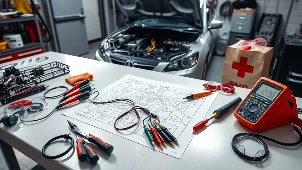
Establish a clean, dry workspace and guarantee you have unobstructed access to the area you’ll be testing. Before you begin, assess the environment for moisture, dust, and trip hazards, and clear unnecessary items. Set up a dedicated work surface with stable height to reduce wrist strain and improve measurement accuracy. Arrange tools in a logical order: meter, probe tips, insulated pliers, and a non-conductive mat. Confirm power is off and lockout procedures are in place if working near sources. Maintain organized cable management to prevent snagging or accidental disconnections. Your workflow should emphasize consistency: label components, annotate diagrams, and document test results immediately. For safety gear, wear non-slip footwear, insulated gloves, and eye protection against debris and arc events. Use a flashlight or headlamp for focused illumination and keep fire safety gear accessible. Train your focus on precision, repeatability, and disciplined inspection to minimize risk and maximize reliability.
Reading Circuit Paths: From Power Source to Load

Where does power travel first, and how can you trace it accurately from source to load? You map a clear path by following the circuit from the main supply through breakers, feeders, and branch circuits to the final device. Begin at the power source and identify the hot, neutral, and ground conductors, noting their color codes and terminal points. Track each conductor’s route on the diagram, confirming junctions, splices, and protective devices along the way. Verify continuity and compare the diagram’s lines with actual wiring, ensuring no unintended connections exist. Pay attention to junction boxes and cable runs, documenting any de-energized states before inspection. Use a logical sequence: source, protection, distribution, and load. This disciplined approach reveals circuit flow and electrical pathways with precision, reducing ambiguity. Stay mindful of changes in configuration, and annotate discrepancies promptly, so diagnosis remains accurate and instrumentation reflects the true wiring topology.
Tracing a Single Power Rail Through a Diagram
To trace a single power rail through a diagram, start by identifying the rail’s origin—normally the hot conductor from the main service or a dedicated feeder. You then follow the path, noting each junction, breaker, and splice it crosses, while keeping the current rail clearly labeled on your diagram. Use power rail identification markers to prevent confusion as you move from source to load, and confirm connections at each node before progressing. Diagram analysis relies on cross-checking symbols, wire colors, and component placements against the schematic legend. Maintain a consistent tracing rhythm: locate, label, verify, and advance in logical steps. The goal is a clean, continuous path that you can reference quickly during troubleshooting.
| Step | Action |
|---|---|
| 1 | Locate origin |
| 2 | Trace through devices |
| 3 | Mark junctions and terminations |
| 4 | Confirm continuity |
Verifying Connections With Basic Testing Tools
You start by testing with a multimeter to establish baseline voltage levels and continuity. Then run simple continuity checks to confirm uninterrupted paths between connectors, cables, and components. Finally, trace the power paths to pinpoint where a break or impedance may be limiting flow.
Test With Multimeter
Testing connections with a multimeter starts by establishing the circuit’s baseline: verify power is off, select the correct range, and check probes for proper contact before taking any readings. You’ll set multimeter settings to the appropriate mode, then measure voltage across the suspected points to confirm expected levels. Keep one probe steady at a reference node while the other sweeps the path, noting any unexpected fluctuations. Document readings precisely, including units and whether measurements are DC or AC. Use proper technique to avoid introducing resistance, and hold the probes perpendicular to conductors for stable contact. Don’t jump ranges unnecessarily; move only when readings stabilize. If readings diverge from diagram expectations, recheck connections, grounds, and routing. This disciplined approach eliminates ambiguity and supports targeted troubleshooting.
Continuity Checks
Continuity checks use a basic tester to confirm that a path is complete and unbroken. You’ll approach the circuit in a controlled sequence, establishing a reference point, then probing each segment for continuity. Begin with thought-out test points, label them, and maintain consistent probe contact to avoid false readings. With a continuity tester or multimeter set to the buzzer or ohm range, verify that resistance is near zero or within acceptable limits across each segment. Document any breaks, spikes, or intermittent readings as troubleshooting techniques, noting logical causes such as loose connections, corrosion, or damaged insulation. Compare findings to your wiring diagram, updating it as needed. Keep paths isolated during testing, and restore circuits only after confirming uninterrupted continuity. This discipline supports reliable troubleshooting techniques and accurate diagnoses.
Pinpoint Power Paths
Pinpointing power paths builds on the continuity checks by focusing on where current actually flows through the circuits. You approach this with purpose, using basic testing tools to map power flow from source to load. Begin at the origin, verify supply presence, and follow conductors along the diagram without assumption. Use a multimeter for voltage readings, a current clamp for live paths, and a test light to confirm illumination where expected. Document each node, noting any unexpected drop or resistance, as these indicate a misroute or loose connection. This is circuit analysis in practice: you translate diagram arrows into measurable reality, validating that each branch carries the intended current. Your goal is a clean, traceable path, free of ambiguity, enabling precise fault isolation.
Documenting Findings and Noting Anomalies
You should document findings in a clear log, noting each anomaly with location, symptom, and timestamp. Maintain traceability by recording consistency checks and any deviations from expected wiring behavior. This initial discussion sets the framework for capturing observations, organizing data, and supporting subsequent analysis.
Noting Anomalies Clearly
Documenting findings begins with clear, deliberate notes: every anomaly should be described precisely, with its location, timing, and effect on circuit function. When you record observations, focus on anomaly identification and visual discrepancies that stand out against expected norms. Note whether measurements align with schematic values, and flag anything divergent as a concrete datum, not a supposition. Use concise terms: gauge, continuity, insulation condition, connector integrity, and color coding. Provide a timestamp and the exact connector or node name, then relate the anomaly to its impact on operation, safety, or performance. Maintain a neutral tone, avoiding speculation; your goal is a traceable trail for others. This disciplined notation strengthens the diagram’s value and supports reliable troubleshooting.
Documenting Findings Log
In documenting findings, you’ll translate observations into a clear, auditable log that supports reliable troubleshooting. You’ll capture what you see, when you saw it, and why it matters, then organize it for quick reference. Your log becomes the backbone of decisions, not a diary of guesswork. Focus on consistency, traceability, and brevity, so others can reproduce your conclusions. Use precise terms, timestamps, and diagram references, and highlight deviations without overinterpreting. Findings should enable pattern recognition, supporting quicker containment and repair. Record observations with minimal bias, then note next steps or verification tests. Your documented trail should be scannable, searchable, and ready for review.
- finding patterns
- recording observations
- auditable decision points
Trace Consistency Checks
When tracing wiring, start with a baseline: verify each continuity and path against the schematic, noting any deviations as anomalies and recording the exact points, tools, and timestamps involved. You’ll document circuit integrity by confirming expected resistance, topology, and connector orientations, then flag discrepancies with concise summaries. Maintain a consistent notation scheme for pins, nets, and color codes to support fault isolation. For each anomaly, capture contextual data: measurement type, instrument settings, environmental factors, and cross-checks against alternative routes. Preserve versioned diagrams and timestamps to enable traceability. Prioritize actionable findings over narrative; attach recommended corrective actions and verification steps. This disciplined approach reduces drift, supports debugging efficiency, and guarantees you can reproduce results in audits or maintenance windows.
Using Diagrams to Isolate Faults and Plan Repairs
Using diagrams to isolate faults and plan repairs starts by translating the wiring layout into clear, labeled visuals that show circuits, junctions, and color-coded paths. You then use these visuals to pinpoint fault isolation opportunities, tracing power and signal flows from source to load. With precision, map each component’s role, note potential interference, and verify continuity before touching hardware. This visual approach feeds repair planning, letting you sequence tasks, allocate tools, and anticipate side effects. You’ll minimize guesswork by validating each step against the diagram, updating paths as you test sections. The result is a focused, actionable plan that aligns with safety practices and project goals.
- Identify fault isolation points and confirm them on the diagram before proceeding
- Sequence repairs to optimize efficiency and minimize downtime
- Cross-check changes with the diagram to guarantee consistency and reliability
Building a Quick Reference Log for Future Troubleshooting
A quick reference log captures core troubleshooting steps, observations, and outcomes in a concise, searchable format. You build it to support repeatable decisions, not personal notes. Start with date, location, circuit identifiers, and owner contact. Record symptoms in plain terms, then list tested hypotheses and evidence that confirms or refutes them. Include tools used, settings, and any measurements with units. Capture change events: what you adjusted, when, and why, plus the immediate effects on operation. Regularly timestamp entries to enable trend analysis over time. Structure the log for quick scanning: section headers, bullet lists, and standardized codes for common faults. Use it during troubleshooting techniques to compare current issues with past incidents, accelerating diagnosis. For ongoing wiring maintenance, schedule periodic reviews and attach diagrams or photos for reference. Maintain data integrity, back up files, and review completed tasks to tighten future responses. This log empowers deliberate, freedom-minded fault resolution.
Frequently Asked Questions
How Often Should Diagrams Be Updated After Wiring Changes?
You should update diagrams after each wiring change; adopt a strict, disciplined cadence. You’ll perform diagram maintenance promptly, documenting what changed and why. In practice, pair updates with testing results, then archive older versions for traceability. Schedule periodic reviews, but don’t wait for issues to accumulate. Track wiring updates in a centralized log, assign responsibilities, and enforce version control. This keeps your system transparent, auditable, and ready for future developments.
Can Diagrams Show Non-Electrical Components Like Sensors?
Yes, diagrams can show non-electrical components like sensors. You can map sensor integration alongside wiring, labeling inputs, outputs, and power rails so the diagram reflects how sensors interact with controllers. Verify diagram accuracy by cross-checking with hardware specs and field installations. Maintain versioned updates as you add or relocate sensors, and note any COTS module connections. You’ll gain clearer troubleshooting and safer integrations when sensor details are included and kept current.
What Symbols Indicate a Failed Connection or Broken Wire?
A failed connection is usually shown by an open circuit symbol or a break in the line, while a broken wire often appears as a discontinuity or a dashed segment in the diagram. Look for gaps, disconnected junctions, or unusual breaks in conductor paths. In practice, label markers and test points confirm it; trace continuity with a meter. When you identify failed connections or broken wires, document exact locations and replace or repair the affected run.
How to Verify Ground Integrity Across a Complex Diagram?
Ground integrity across a complex diagram requires methodical ground testing and strict continuity checking. You should start by verifying the main chassis ground, then trace each branch to its point of return, measuring with a low-resistance meter. Use a reference node and document all readings. If any path differs, isolate the divergent segment and re-test. Think of it like mapping a river: precise, deliberate, and freedom-fueled in pursuit of a solid ground.
Are There Industry Standards for Diagram Version Control?
Yes, there aren’t universal legal mandates, but industry practice favors formal diagram maintenance and version history controls. You should adopt a documented process: assign unique version identifiers, archive prior states, and clearly timestamp changes. Track edits, rationales, and approvals to guarantee traceability. Use baseline cycles, access controls, and rollback capabilities. In practice, this supports compliance, audits, and collaboration, while still giving you the freedom to evolve diagrams with confidence.