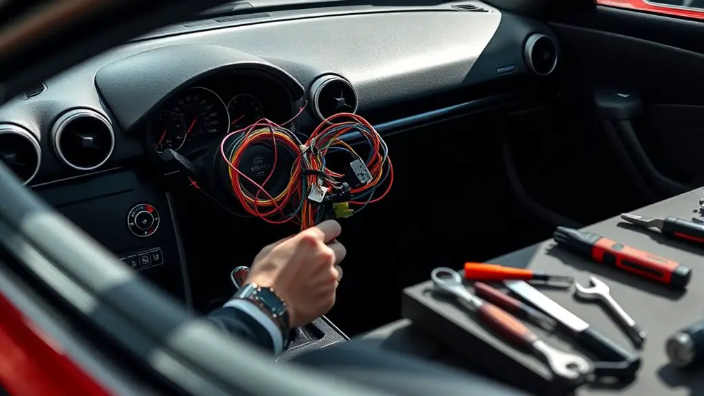
Safety Checklist After Repairing SRS Wiring Harness
After repairing the SRS wiring harness, you should verify continuity and insulation with power off, tracing each run for pinched or damaged sections and recording any resistance outliers. Check grounding paths and guarantee a clean battery negative connection, then inspect all connectors for corrosion or bent pins, reseating as needed. Perform a fault code readout, clear safe codes, and re-scan for persistent issues. Finally, power up stepwise, monitor for abnormal sounds or lights, and note what adjustments remain; more specifics await you.
Verifying SRS Continuity and Integrity
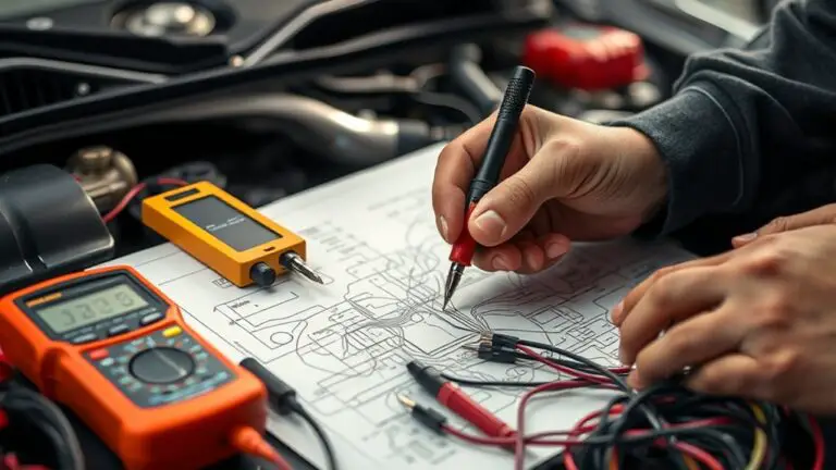
To verify SRS continuity and integrity, start by disconnecting the battery and isolating the airbag control module to prevent accidental deployment. You’ll methodically inspect the SRS system using approved procedures and certified wiring diagrams, ensuring test points align with the manufacturer’s baseline. Measure continuity across harness pins without applying power, recording any resistance outliers that exceed specification ranges. Confirm that connector seals remain intact and that there’s no corrosion, fraying, or pin displacement in the wiring diagrams’ reference sections. Validate that the clock spring path remains unobstructed and that the steering column wiring is compliant with impedance targets. Document all findings with timestamped notes, batch numbers, and component IDs, then re-check after any observed anomaly is corrected. Maintain strict adherence to safety guidelines and standards-driven checks, prioritizing precise, repeatable results. You want a reliable SRS system that supports safe driving freedoms while remaining within verified engineering tolerances.
Ensuring Proper Grounding and Battery Safety
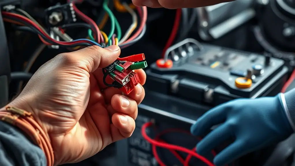
Ensuring proper grounding and battery safety is essential for reliable SRS operation; begin by verifying a solid chassis ground and a clean battery negative connection, free of paint, corrosion, or oxide layers. You’ll establish a dependable reference and reduce noise susceptibility during diagnostic checks.
Ensuring solid chassis grounding and clean battery negative connection for reliable SRS diagnostics.
- Confirm grounding techniques at all chassis points, tightening to spec and inspecting for frayed straps or loose bolts.
- Inspect battery terminals and cable routes, ensuring no overlap with moving parts, heat sources, or routing hazards.
- Verify battery maintenance practices, including terminal cleanliness, correct electrolyte levels where applicable, and secure auxiliary connections.
- Document test results and recheck after any service to guarantee sustained integrity and predictable system behavior.
Inspecting Connectors for Damage or Corrosion
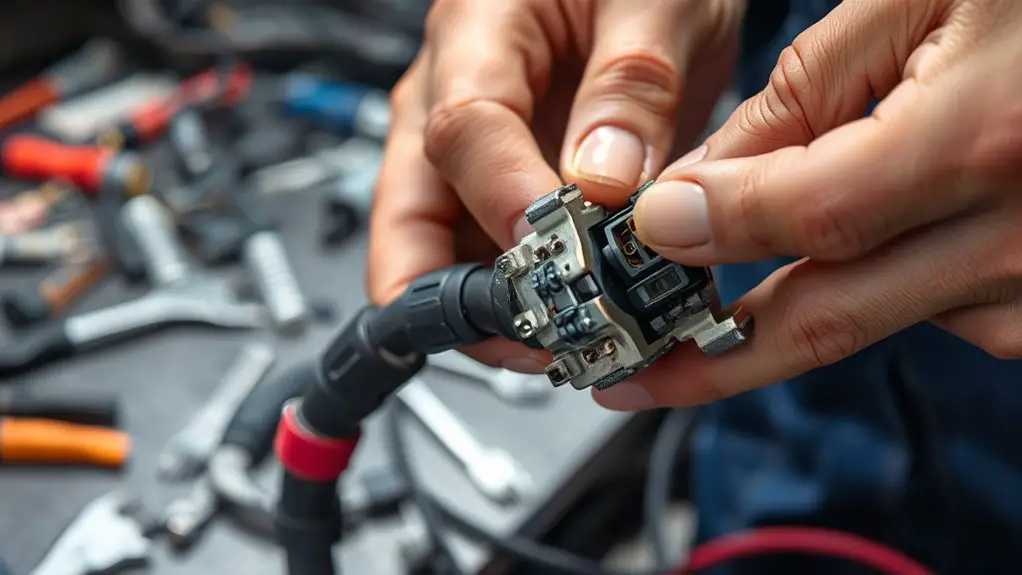
You’ll start by inspecting each connector’s surface for nicks, cracks, or deformed pins, noting any abnormalities that could affect seating. Look for corrosion indicators such as greenish or whitish residue, pitting, or whisker-like deposits around contact surfaces. Document findings succinctly and compare them against the established corrosion risk indicators to determine if further cleaning or replacement is required.
Connector Surface Check
A careful surface check should start with a visual inspection of each connector housing and contact interface for any signs of wear, heat damage, moisture intrusion, corrosion, or physical deformities. You’ll verify alignment, seating, and latch integrity before proceeding to cleaning and surface prep.
- Inspect for micro-cracks and bent pins, noting any deformation in the contact area.
- Document dirty or contaminated surfaces, then perform connector cleaning and surface preparation per protocol.
- Check for residual residue after cleaning, ensuring no debris remains that could impede connection.
- Confirm that housings seal properly and that mating surfaces are smooth, dry, and free of corrosion indicators.
Corrosion Risk Indicators
Corrosion can develop quietly at connector interfaces, so start by examining both contact surfaces and housings for any signs of oxidation, green or brown discoloration, pitting, or corrosion streaks. You’ll inspect terminal alignment, mating force, and shield integrity, noting any looseness or coating wear that hints at moisture ingress. Look for dielectric discoloration inside seals, melted potting, or compromised gaskets, and verify that fasteners show uniform torque without streaking or fretting. Compare observed conditions against manufacturer standards, documenting any deviations. Pay attention to environmental factors—exposure to salt spray, humidity, temperature cycling, or chemical cleaners—that accelerate corrosion risk. Prioritize corrosion prevention through timely cleaning, proper drying, and appropriate dielectric compound, ensuring reliable SRS wiring harness performance without unnecessary downtime.
Checking Sensor and Airbag Module Wiring Routes
To guarantee reliable operation after repairs, begin by tracing each sensor and airbag module wiring route from connector to component, verifying that no harness is pinched, cut, or routed over sharp edges or moving parts. You’ll assess sensor placement and wiring insulation to prevent false readings or shorts, ensuring routing stays clear of belts, heat sources, and pinch points. Maintain a clean, repeatable path that respects factory guidance and protective loom coverage.
1) Inspect every run for secure fasteners and proper slack, noting any abrasion risk.
2) Confirm insulation integrity, replacing damaged sheathing or adding protective sleeves as needed.
3) Validate that routes avoid interferences with airbags, modules, and adjacent harnesses.
4) Document harness topology, labeling connectors and loom segments to support future service.
Proceed with measured, standardized checks, then re-check against fault-free operation expectations to preserve system confidence.
Performing Fault Code Readout and Clearing Procedures
To begin fault code readout and clearing procedures, you’ll verify the correct scan tool setup and vehicle compatibility, then follow the Fault Code Readout Steps to capture all stored and pending codes. Next, apply Clearing Procedures Guidelines to erase relevant codes only after confirming safety verification checks are satisfied, ensuring all modules report no active faults. Maintain traceability by documenting codes read, actions taken, and the final confirmation of a clean readout.
Fault Code Readout Steps
Fault code readout is the starting point for diagnosing SRS wiring issues: you’ll connect the scanner, retrieve stored and current codes, note the exact codes and freeze frame data, and prepare to clear codes only after verifying mechanical and electrical conditions meet safety and repair standards.
- Use diagnostic tools properly to capture all active and historical fault data.
- Record fault code definitions clearly, distinguishing between P-, B-, C-, and U-codes for precise direction.
- Verify freeze frame data reflects current conditions before proceeding.
- Confirm no conflicting codes remain and that power, grounding, and sensor integrity meet standards.
This disciplined approach guarantees you preserve safety margins while you prepare for the next steps in clearing procedures.
Clearing Procedures Guidelines
Clearing fault codes should only occur after you’ve verified that mechanical repairs and electrical conditions meet all safety and performance standards. You perform fault code readout with structure, then proceed to clearing using documented steps and limits. You confirm fault presence, document codes, and guarantee no pending or intermittent faults remain. You then clear per procedure, re-scan to confirm reset success, and log outcomes for traceability. If codes return, reassess wiring harness maintenance and SRS wiring integrity before reattempt. Maintain strict sequence to avoid masking faults. This approach reflects SRS troubleshooting techniques and emphasizes disciplined, repeatable actions. Expect consistency, not guesswork, and preserve system readiness through careful validation and controlled testing.
| Step | Description |
|---|---|
| Readout | Verify and record codes |
| Clear & Verify | Clear, re-scan, log results |
Safety Verification Checks
After guaranteeing the mechanical repairs and electrical conditions meet safety and performance criteria, you’ll validate system readiness through fault code readout and subsequent clearing procedures. You’ll methodically verify the SRS system integrity, confirm wiring safety, and document results to guarantee compliant operation. Follow these steps to maintain discipline and autonomy:
- Read fault codes with approved diagnostic tools, noting active and historical codes.
- Confirm all monitored parameters reset to baseline after clearing, verifying no reoccurring faults.
- Clear codes only after confirming proper corrective actions and rechecking wiring harness connections.
- Re-test system functionality in a controlled environment, observing intermittent alerts and guaranteeing stable engine and restraint deployment readiness.
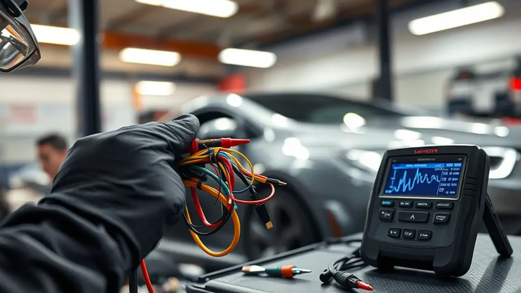
Verifying Demands and System Readiness With Scan Tool
To verify demands and system readiness, start by connecting the scan tool and establishing a stable baseline for all modules involved in the SRS network. You’ll compare live data against expected states, then monitor for consistent readings across cycles. Use scan tool functionality to access ignition status, module fault codes, and communication bus activity. Document any deviations and prepare diagnostic procedures to isolate discrepancies without triggering unnecessary alarms. Maintain a methodical pace, confirming each module’s readiness before advancing.
| Step | Action |
|---|---|
| 1 | Connect scan tool and verify baseline |
| 2 | Read fault codes and confirm no active faults |
| 3 | Verify data stream consistency across modules |
Proceed only after confirming stability, validating power rails, and ensuring no transient errors remain. This approach keeps you aligned with standards-driven practices while preserving your sense of freedom to troubleshoot efficiently, without compromising safety.
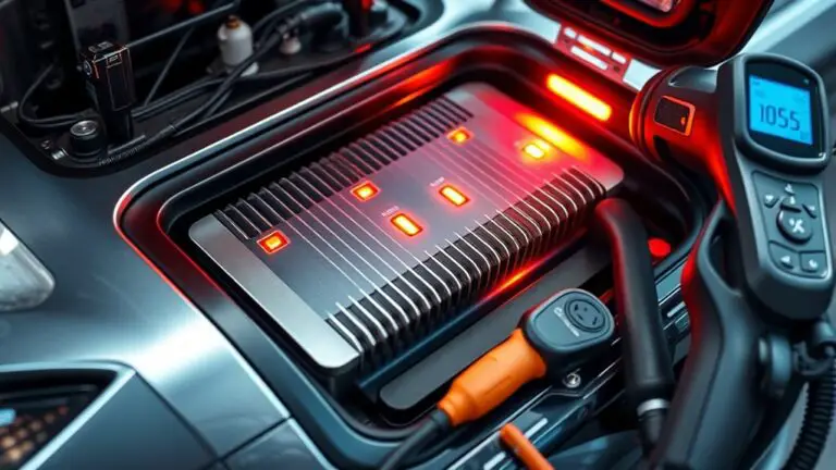
Conducting a Safe Power-Up and Initial System Test
Initiate the power-up in a controlled sequence, verifying that all safety interlocks and protective circuits are engaged before enabling main power. You’ll follow strict power up procedures to guarantee reliability, then perform initial testing with diligence and restraint. Your focus is on clear, repeatable steps that minimize risk while validating functionality.
- Confirm harness connections are secure, no loose pins, and no physical damage persists in any sensor branch.
- Energize subsystems one at a time, listening for abnormal hums or resonance and halting if anything deviates from baseline.
- Validate core safety circuits respond to simulated fault conditions within defined thresholds.
- Log each parameter, comparing against documented standards to certify compliance before full system activation.
Maintain calm, deliberate pace to preserve control. If anomalies occur, suspend power, reassess, and document findings. This approach supports reliable power up procedures and accurate initial testing, aligning with a freedom-to-operate mindset while upholding stringent safety norms.
Interpreting Warning Lights and Fault Codes Post-Repair
When you see warning lights or fault codes after repair, start with a disciplined, stepwise assessment: identify the active indicators, note the exact code or sequence, and reference the repair/diagnostic documentation to distinguish between transient, recoverable signals and persistent faults. You should verify power state, connector integrity, and recheck grounding paths before drawing conclusions. Catalog each symbol, its color, and its position in the cluster to map to warning light meanings and potential system impacts. For fault codes, capture the full alphanumeric string, timestamp, and any related sensor readings. Consult the code handbook to interpret significance, separating routine confirmations from actionable faults. Track whether codes reoccur after a cycle test; transient signals often clear on reset, while persistent codes require targeted remediation. Document findings clearly, confirm reset procedures, and maintain a standards-driven log to support safe, informed decision-making.
When to Seek Professional Help for SRS Concerns
After completing the initial checks and documenting warning lights and fault codes, you’ll know when professional help is warranted. You should seek professional diagnostics when SRS symptoms persist or worsen after repairs, or you notice intermittent or unexpected behavior in airbag indicators. Rely on standards-driven evaluation to prevent secondary risk and guarantee proper, repeatable results.
- Persistent warning lights despite rechecks
- Unclear fault codes or inconsistent diagnostic readings
- Visible degradation in wiring, connectors, or harness routing
- Any doubt about system integrity or passenger safety implications
Professional involvement guarantees thorough testing, calibration, and validation against OEM criteria. You’ll preserve freedom to drive with confidence, knowing the chain of custody for safety-critical components remains intact. Avoid improvised fixes that compromise protection. Documented diagnostics, traceable repairs, and verified service history are essential. If you encounter any of the listed conditions, schedule a qualified assessment promptly. Remember: precise, methodical steps now prevent risk later and align with SRS safety standards.
Frequently Asked Questions
How Long Should SRS Function Be Tested After Repair?
“Time is money.” You should perform SRS functionality testing for at least 30 minutes of steady operation, then verify fault-free results before wrapping up. You’ll log diagnostic data, monitor for anomalies, and confirm no airbag system faults remain. Use repair verification methods that include functional tests, wiring continuity checks, and module reset verification. Follow standards-driven procedures, document outcomes, and guarantee the vehicle’s safety readiness before release. You’re exercising disciplined freedom with responsible testing.
Can I Drive Before a Final Airbag Deployment Test?
No, you should not drive before a final airbag deployment test. You must confirm airbag safety and complete wiring inspections first, following standards-driven procedures. If the test isn’t finished, stay off the road and isolate the vehicle. You’ll want to verify fault codes, ascertain SRS system readiness, and recheck connections. Only after passing the final deployment test should you proceed. Adhere to safety guidelines, keep movements controlled, and document every step for accountability.
What if Warning Lights Stay on After Repair?
If warning lights stay on after repair, you should not drive it until you complete proper diagnostics. Perform warning light diagnostics and verify fault codes, sensor connections, and module communication. Re-check the SRS system troubleshooting steps, ensuring grounding integrity and harness integrity. Follow standards-driven procedures, document findings, and confirm zero codes before any road test. You deserve freedom, but prioritize safety, repeat the diagnostic cycle if needed, and consult a professional if lights persist.
Are Aftermarket Sensors Acceptable for SRS Repair?
Aftermarket sensors aren’t automatically acceptable for SRS repair; you should confirm OEM-level compatibility and support. You’ll want to verify aftermarket compatibility with your vehicle model and guarantee sensor performance meets safety standards. If you value freedom, proceed only with trusted brands and full diagnostic validation, including steering wheel position, airbag module readiness, and fault codes. Don’t overlook proper wiring, harness integrity, and reprogramming requirements to avoid false alarms or deployment failures.
How to Dispose of Damaged Airbag Components Safely?
To dispose of damaged airbag components safely, you must follow proper disposal procedures for hazardous materials. Do not discard them with regular trash; isolate, seal, and transport per local regulations. Contact your local hazardous waste facility or licensed automotive recycler for guidance and drop-off. Use certified containers and document the chain of custody. You’re responsible for safety; comply with standards, protect others, and guarantee the parts aren’t released into the environment.