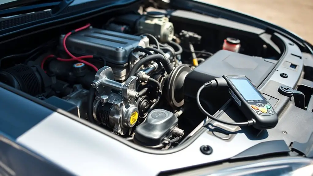
Step-By-Step: Diagnosing AC Not Engaging While Idle in Your Sedan AC
If your sedan’s AC isn’t engaging at idle, start with the thermostat: confirm cooling mode is active and the target temp is sane, then compare the display to the cabin temp. Check fuses and relays, listening for a relay click and inspecting wiring for corrosion or loose connections. Verify the AC clutch engages on command, then inspect refrigerant charge and for leaks. Finally, examine grounds and electrical paths; staying on task will reveal where trouble hides, and more steps await.
Checking the Thermostat and Temperature Settings
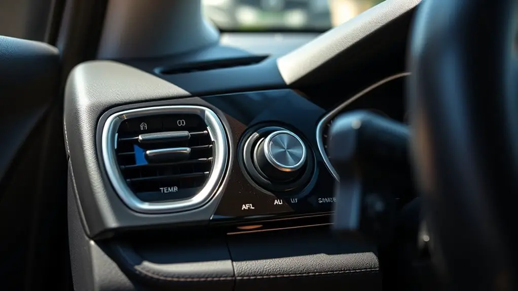
Begin by verifying the thermostat setting and confirming the mode is correctly selected. You’ll walk through with a clear, methodical approach, tracing the control path from user input to climate output. First, confirm the display reflects cooling mode and a measurable target temperature. If the setting appears off, reset to a known good configuration and recheck. Next, assess the temperature gauge against the actual cabin temperature; note discrepancies and whether they persist after calibration. Perform thermostat calibration by observing the system response to deliberate, small adjustments of the setpoint, and record the time lag until the compressor engages. If the gauge reads consistently higher or lower than ambient, investigate sensor placement, wiring integrity, and potential obstruction in the control circuit. Maintain concise notes for future reference, and confirm the system responds predictably to modest changes. This disciplined check helps you preserve freedom through reliable comfort control.
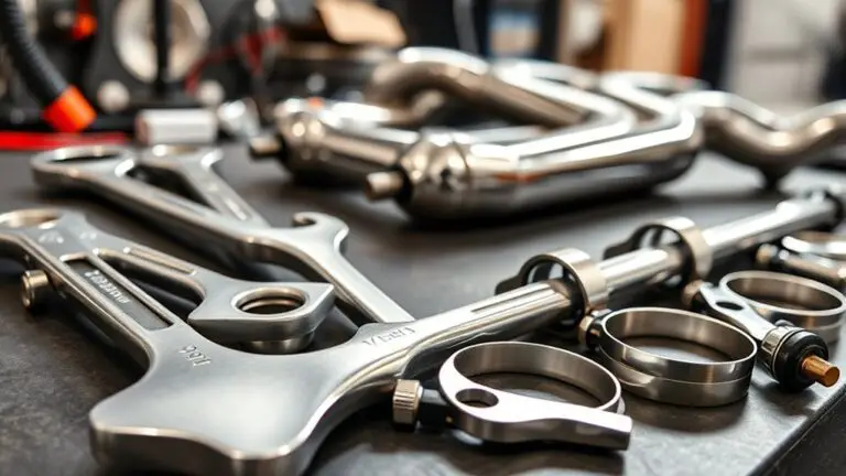
Inspecting Fuses and Relays for the A/C System

After confirming the thermostat’s behavior, the next reliable checkpoint is the electrical path to the A/C system. You’ll inspect fuses first, locating the fuse box and identifying the A/C-related fuses. Check fuse types and continuity with a Multimeter or a trusted fuse tester, replacing any that are blown. Note color, amperage rating, and labeling to avoid mismatches. Next, assess relay functions by locating the A/C relay in the fuse/relay panel. Listen for a solid click when the ignition is on, and test the relay coil resistance if needed. Swap in a known-good relay to confirm operation, but only when the circuit is off and safely accessible. While testing, verify wiring harness connectors are fully seated and free of corrosion or burns. Document findings clearly, then recheck the system’s idle engagement. These steps eliminate common electrical faults without venturing into mechanical clutch territory, preserving your freedom to diagnose with confidence.
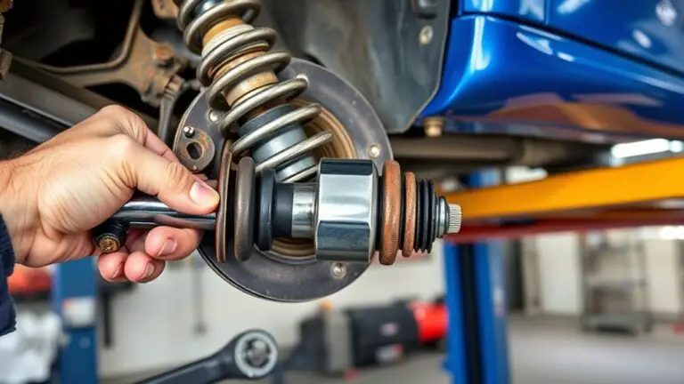
Verifying Clutch Operation on the AC Compressor
To verify clutch operation, you’ll confirm whether the AC compressor clutch engages when commanded. Check both the electrical signal and the clutch’s mechanical response, noting any lag or failure to engage. If the pulley spins without clamping, pursue electrical or relay issues before inspecting the clutch coil and wiring.
Clutch Engagement Check
If the AC isn’t cooling, start by verifying the clutch engagement on the compressor; a clicking or grinding sound can indicate the clutch is energizing, but the pulley may not be driving the compressor if the belt is loose or slipping. You’ll inspect for the clutch plate’s movement and listen for proper engage timing as the system cycles. Check for smooth engagement without chatter, and confirm the magnet coil isn’t weak or open. Reasons for engagement issues include clutch malfunction and worn linkage. When you observe hesitation, note the bearing noise and belt tension. Table provides a visual guide:
| Action | Expected Result | Common Cause |
|---|---|---|
| Inspect coil | Clutch engages fully | Weak magnet, resistance |
| Observe belt | No slip | Worn pulley, loose belt |
| Listen for chew | Clean engagement | Debris, misalignment |
| Check tension | Proper drive | Loose belt, tensioner failure |
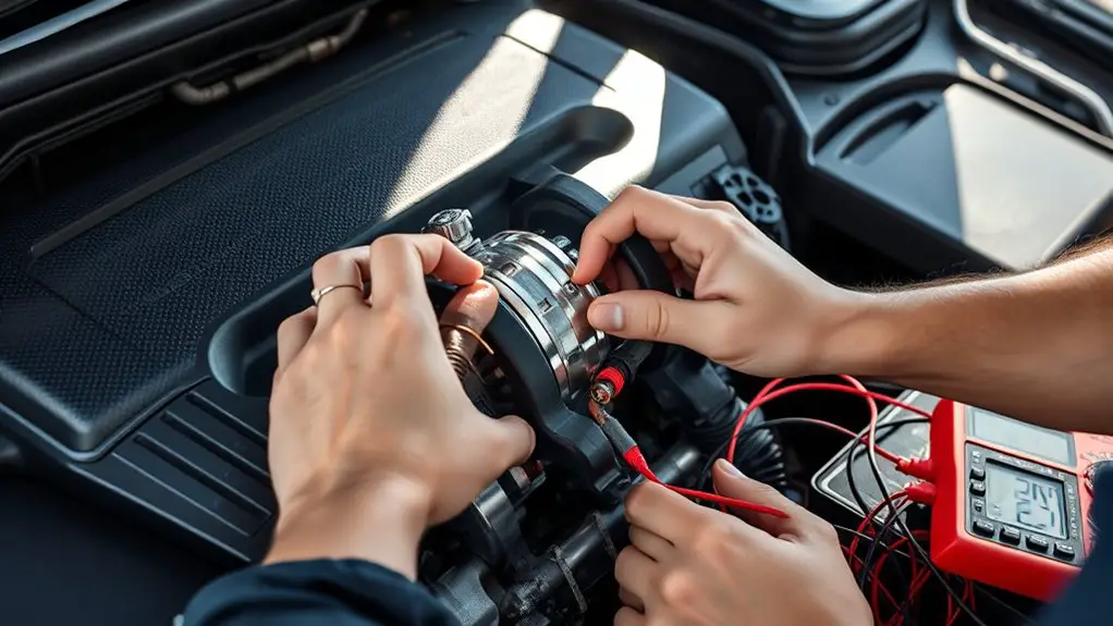
Electrical Signal Verify
Electrical signals from the clutch control circuit must be verified directly at the compressor. You’ll test for proper voltage and ground reference at the clutch coil during idle and commanded clutch engagement. Use wiring diagrams to identify the coil terminals and trace the control path from the A/C control module or pressure switch to the compressor. With the engine running and the AC on, measure coil resistance and observe for intermittent drops or opens. If voltage is present but the clutch doesn’t engage, you’re facing an electrical fault rather than a mechanical jam. Document switching behavior, confirm grounds are solid, and inspect inline fuses and relays. This is electrical troubleshooting—precise, repeatable, and essential for reliable clutch operation.
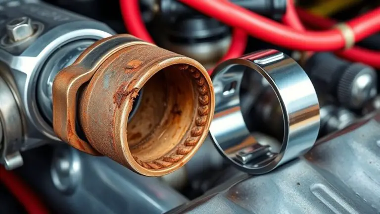
Examining the Refrigerant Charge and Leaks
So, start by checking the refrigerant charge and scan for leaks using a calibrated gauge set and a UV or electronic leak detector; if the system’s pressure is low, it points to undercharged refrigerant, a common cause of AC not engaging. You’ll document readings, verify ambient conditions, and compare with factory specifications, ensuring accuracy before proceeding. Focus on precise steps: connect the gauges, observe high- and low-side pressures, and note temperature-entropy data to assess charge state. If low, consider refrigerant recovery procedures before any recharge, following safety and environmental guidelines. For leak detection, sweep accessible joints, hoses, and the condenser area with UV dye or electronic sensors, marking all found seepage for repair. Address small seepages promptly to prevent future losses. After repairs, perform a controlled recharge to the specified charge, then recheck pressures and system performance. Maintain clean, professional records to support eventual refrigerant recovery and ongoing leak detection monitoring.
Diagnosing Electrical Connections and Grounds
You’ll start by verifying grounding integrity and ensuring all chassis and engine grounds are clean, tight, and free of corrosion. Next, check electrical connectivity at the main harness, relays, and fuses, looking for loose or damaged pins and ensuring good contact. Finally, test for continuity and resistance paths to critical components to confirm there are no opens or high-resistance joints compromising the control signals.
Grounding Integrity
Grounding integrity is the foundation of reliable electrical operation; when grounds are compromised, symptoms can mimic other failures, so start by confirming all chassis and battery negative connections are clean, tight, and corrosion-free. You’ll verify solid grounding paths, inspecting any paint or debris that breaks contact, and reseating bolts to spec. If you detect resistance, reattach with dielectric grease and torque to manufacturer spec. Use targeted grounding techniques to reduce noise, verify the engine block, body grounds, and alternator ground strap are continuous. Conduct a quick continuity test across key points, noting any voltage drop during idle. Grounding issues often reveal themselves as intermittent clutching or fan cycles. Table illustrates common pairs and fixes.
| Point | Action |
|---|---|
| Chassis to battery | Clean, tight, corrosion-free |
| Ground strap | Inspect, reseat, torque to spec |
| Continuity test | Monitor for voltage drop |
Electrical Connectivity
Electrical connectivity is the next step because clean, reliable electrical paths are what let the system respond correctly when you demand power. You’ll verify that grounds are solid and free of corrosion, then inspect connections at the blend of harnesses and relays. Look for loose pins, cracked insulation, and pinched wires that could interrupt current flow. Use a structured approach: reference the electrical diagram, trace conductors from the power source to the AC control module, and note any abnormal resistance readings. Perform circuit testing with a multimeter, confirming continuity and proper voltage at key junctions. Document findings, then recheck after any tightening or reseating. A clean circuit, confirmed by testing, reduces ambiguity and speeds safe, confident decisions.
Assessing the Cabin Air Filter and Airflow
If the climate control isn’t delivering airflow, start by inspecting the cabin air filter and the system’s airflow path for obstructions. You’ll disconnect the filter housing, remove the dirty filter, and inspect for debris along the intake duct. If the filter is saturated or fine particles cling to the pleats, note that filter replacement is likely necessary to restore unobstructed flow. With the filter out, check for loose, cracked, or disconnected ductwork, and verify that the blower motor shaft isn’t rubbing a seized fan wheel. Listen for abnormal whines or grinding that signal bearing wear. Reassemble only after confirming clear pathways from the cabin to the blower housing. After replacing the filter, run a short test cycle on high, observing for even distribution of air from all vents. This inspection supports airflow improvement while preserving system integrity and comfort, aligning with your desire for reliable, liberated driving.
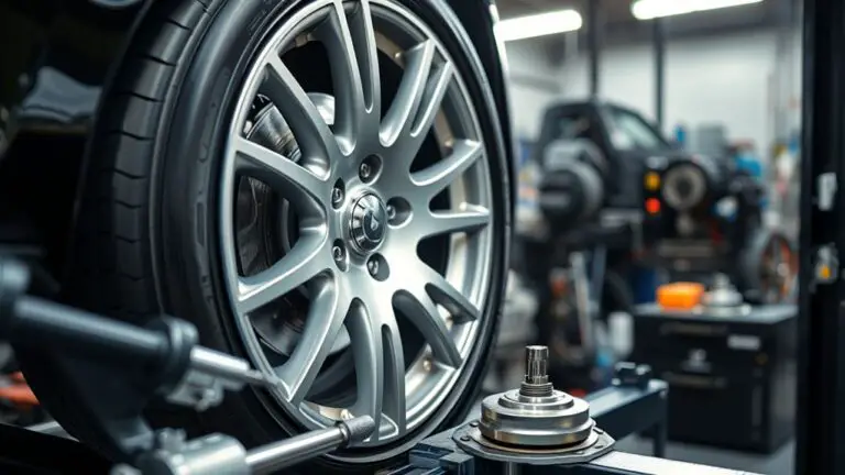
Testing the Condenser Fan and Cooling System
When testing the condenser fan and cooling system, start by confirming the engine is cool and the A/C is off before you inspect for obvious damage or debris around the condenser fins and fans. Next, visually verify condenser integrity, checking for bent fins, leaks, or loose mounting brackets that could impede airflow. If you detect debris, perform condenser cleaning with a soft brush or compressed air, directing airflow from the center outward to avoid bending fins further. With the hood open, manually rotate the radiator fan (when safe) to confirm free spin and listen for binding, grinding, or electrical resistance that suggests a motor or relay issue. Measure electrical resistance at the fan wiring and fuse box; replace a blown fuse or faulty relay as needed. Test for proper fan operation by starting the engine—wait for the thermostat to signal cooling and verify the condenser fan engages smoothly. Document findings for future reference and avoid unnecessary repairs.
Interpreting Diagnostic Codes and When to Seek Help
After confirming the condenser and cooling system are functioning, you’ll need to interpret the diagnostic codes the vehicle’s computer may store. You’ll use diagnostic tools and code scanners to read the PCM, then translate codes into actionable steps. Treat each code as a data point, not a verdict, and proceed with a controlled plan.
- Identify whether a code is active or historical, prioritizing active faults that affect idle engagement.
- Cross-check related subsystems (AC, powertrain, sensors) to confirm a consistent failure pattern.
- Note code definitions, required repairs, and potential bypass risks before deciding to proceed.
- Decide whether you can DIY safely or should seek professional help, especially with refrigerant, electrical, or sensor issues.
If codes point to electrical faults, refrigerant pressure, or sensor malfunctions, consider expert diagnosis. When in doubt, consult a qualified technician using your code scanners as a prepared, freedom-driven navigator.
Frequently Asked Questions
What if the A/C Still Doesn’T Engage After a New Thermostat Install?
If it still won’t engage after a new thermostat install, check thermostat calibration and confirm it’s signaling the compressor correctly. Next, verify refrigerant levels aren’t too low or overcharged, as that stalls operation. Inspect the relay, fuse, and wiring for bad connections. Test the pressure switch and defrost sensor for faults. If issues persist, use a diagnostic scanner to read fault codes, then adjust or replace components accordingly, maintaining a calm, freedom-loving, methodical approach.
Can a Blown Belt Prevent the AC From Engaging While Idle?
Yes, a blown belt can keep the AC from engaging while idle. You should perform a belt inspection for cracks, fraying, glazing, or looseness, then test AC performance with the belt properly tensioned. If the belt is damaged, replace it and recheck engagement. If it still won’t engage, investigate compressor clutch and electricals. Stay precise, methodical, and free-spirited enough to trust your diagnostic instincts.
How Do Ambient and Engine Temps Affect Idle AC Engagement?
Ambient and engine temps can delay idle AC engagement. When ambient temperature is high, compressor clutch may ramp more gradually as you’ll notice slower cooling. Engine temperature influence matters too: if the engine sits cool, idle RPMs stay steady and AC engages sooner; if overheated, you may see delayed engagement or reduced performance until temps normalize. Monitor gauges, and consider cooling system health, fan behavior, and ambient conditions—these factors drive reliable, precise engagement.
Could Idle AC Issues Stem From Hybrid/Electric Vehicle Systems?
Yes, idle AC issues can stem from hybrid systems and electric issues. You’ll want to isolate whether the compressor engages when in EV mode, check battery cooling requests, and review inverter and traction motor interactions. Look for derated or blended operation signals, degraded parasitic loads, and sensor faults in hybrid control logic. If you notice lag or abrupt cycling, test AC control logic against the hybrid system’s state-of-charge and cooling demand to diagnose precisely.
Is a Malfunctioning Climate Control Module Common in This Symptom?
A malfunctioning climate control module isn’t usually the first culprit for idle-engaged AC failure, but it can be a contributing one. If you notice inconsistent cooling or delayed on-off cycling, suspect the climate control module replacement might be needed after solid electrical checks. Start with fuses, relays, and sensor inputs, then test the module’s communication with the AC compressor. If symptoms persist, schedule a professional evaluation to confirm module replacement is warranted. Stay methodical and decisive.